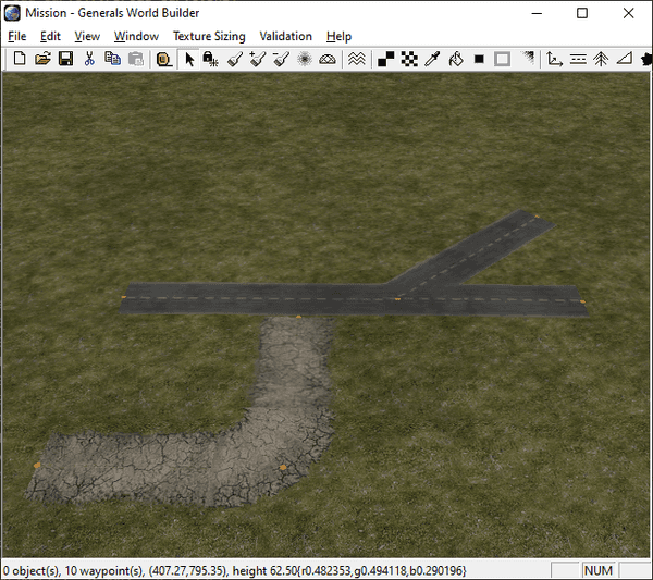
Figuring out how to render the roads correctly in OpenSAGE turned out to be a little more challenging than expected. This is the second post in a series describing the journey. In part 1 we created a test map with some roads and looked at the textures for the different road types.
Now that we finished our road network, let's save the map and see how all this information is stored in the map file...or rather, how it's not stored. While we can observe the described behavior (close endpoints are merged to form connected roads and crossings) in World Builder, the map file doesn't really care about these connections. Roads are not stored as separate objects. Instead, there's simply a pair of map objects for each road segment (the same kind of objects that are used for trees, buildings, units, props, etc) with some flags.
For our map above, it looks like this:
| ObjectType | X | Y | RoadType |
|---|---|---|---|
| TwoLaneDarkDotted | 191 | 412 | Start |
| TwoLaneDarkDotted | 346 | 410 | End |
| TwoLaneDarkDotted | 450 | 407 | Start |
| TwoLaneDarkDotted | 346 | 410 | End |
| TwoLaneDarkDotted | 471 | 540 | Start |
| TwoLaneDarkDotted | 346 | 410 | End |
| TwoLaneOld2 | 288 | 288 | Start | TightCurve |
| TwoLaneOld2 | 182 | 289 | End |
| TwoLaneOld2 | 288 | 288 | Start | TightCurve |
| TwoLaneOld2 | 291 | 393 | End |
The RoadType is a bit field that contains information about whether this is a start or end point and about the curve type (the default is BroadCurve, whereas TightCurve and Angled have their own bits).
So all we know are the start and end positions of all road segments, but there's no information about the connections of these segments. It appears that two segments of the same type are connected when they share one of their positions. In order to correctly draw the different road textures (remember, there are different types of crossings), we need to create a data structure that can be reasoned about more easily. We'll do that in part 3.
