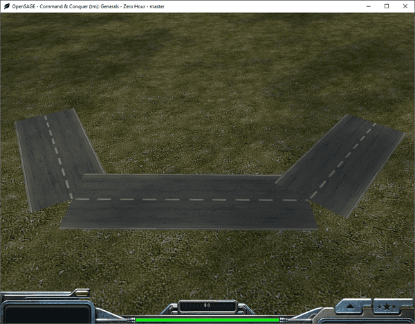
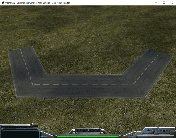
Figuring out how to render the roads correctly in OpenSAGE turned out to be a little more challenging than expected. This is the fifth post in a series describing the journey. In the last post, we rendered road segments for the first time, but they are still disconnected and overlap each other:
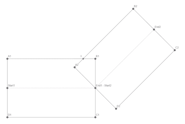
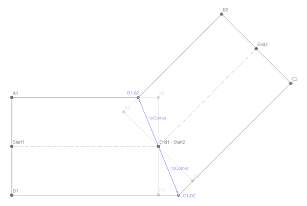
Ignoring the different curve types for now, let's consider angled connections. We have two overlapping rectangles (one for each edge) that have an intersection point at the common node position (End1 - Start2). We want to modify the two corner points B1 and A2 so that they share the same position X (and then do the same for the other corner).
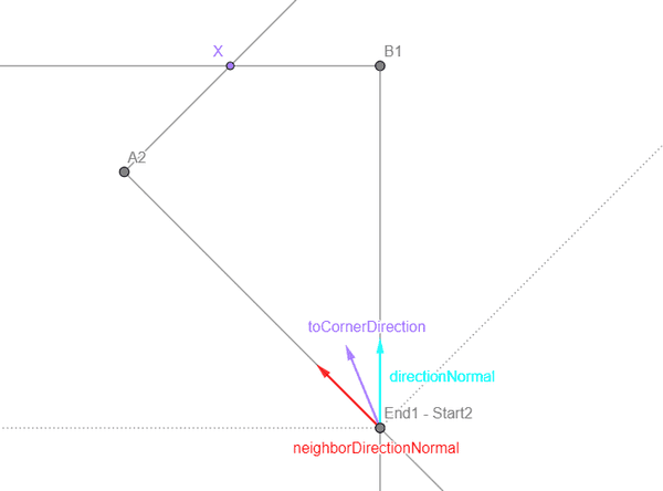
So, how can we calculate X? With the graph we created in part 3, we can easily find the neighbor segment and its start and end position. For both the current and the neighbor segment, we can calculate the direction vector's normal (directionNormal and neighborDirectionNormal). We can calculate the average of these two vectors, normalize it and get a direction vector toCornerDirection pointing from the node position towards X.
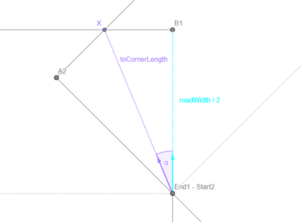
Now we need to multiply this direction vector with the correct length to get to X. Considering the right-angled triangle End1 - Start2, X, B1, we know that
cos α = (roadWidth / 2) / toCornerLength .
cos α can be calculated without actually knowing the angle by calculating the dot product of directionNormal and toCornerDirection.
This gives us
toCornerLength = (roadWidth / 2) / Vector3.Dot(directionNormal, toCornerDirection)
and finally the vector to X:
toCorner = toCornerDirection * toCornerLength
Now we can calculate the new shared corner positions B1 - A2 and C1 - D2 by adding and subtracting the vector to the shared node position.
As we saw in the last post, it's also important to adjust the U texture coordinate accordingly to avoid distortions.
Next time, we'll take a first look at crossings.
