Figuring out how to render the roads correctly in OpenSAGE turned out to be a little more challenging than expected. This is the eighth post in a series describing the journey. Last time, we started rendering crossings and found the formulas for calculating the rectangles in world coordinates based on the parameters RoadWidth and RoadWidthInTexture.
Texture coordinates
Now we need to find the coordinates of these rectangles in the road texture, just as we did for the straight roads in part 4.
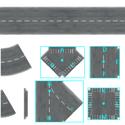
Let's start by dividing the whole texture into a 3x3 grid. The center of the T crossing is located at the center of tile [2, 3], and the center of the X crossing is located at the center of tile [3, 3]. In texture space, they are located at [3/6, 5/6] and [5/6, 5/6] respectively. However, as we found out in part 4, the engine approximates 1/6 as 1.666, truncating all decimal places after the third. This also happens for the center of tile two, which is not 0.5, but 0.498 (3 * 1.666).
We also already know that the default road width of 0.25 is scaled with the factor RoadWidthInTexture. Now we only need the lengths of the small extruding stubs. By measuring some textures of different sizes, we can find out that it is 0.004 regardless of RoadWidthInTexture.
Using the variables
| Name | Abbreviation | Value |
|---|---|---|
| Half tile width | htw |
0.166 |
| Half road width | hrw |
0.25 * RoadWidthInTexture / 2 |
| Length to incoming road | lti |
0.25 / 2 + 0.004 |
this gives us the following texture coordinates for the T- and X-crossing:
| Crossing type | Left | Top | Right | Bottom |
|---|---|---|---|---|
| T | 5 * htw - hrw |
3 * htw - lti |
5 * htw + lti |
3 * htw + lti |
| X | 5 * htw - lti |
5 * htw - lti |
5 * htw + lti |
5 * htw - lti |
Unfortunately the two Y crossings are a little less straight forward and require some hardcoded numbers (this time, width and height are given instead of right and bottom coordinates):
| Crossing type | Left | Top | Width | Height |
|---|---|---|---|---|
| Symmetric Y | 3 * htw - 0.2 |
0.504 - 0.135 |
0.4 |
0.270 |
| Asymmetric Y | 0.395 - hrw |
0.645 |
1.2 * 0.25 + hrw |
0.335 |
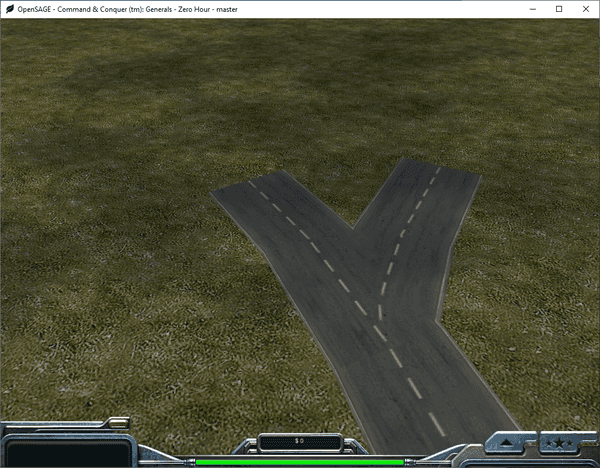
Using these coordinates, we can now render the crossings, but it doesn't look quite right yet:
The crossing texture and the straight road segment textures overlap because the segments all start directly at the node position.
Connection points
We need to move the end points of the incoming road segments outwards to the positions labeled A-M in the image above.
The following table lists the vectors that need to be added to the node positions to get to these connection points (Up, Down, Left, Right, DownLeft and DownRight being unit vectors pointing in the respective directions and Width and Height referring to the rectangles we calculated in the last post).
| Crossing type | Position | Vector from |
|---|---|---|
| Symmetric Y | A | Up * (0.269 * Height) |
| Symmetric Y | B | DownRight * (0.547 * RoadWidth) |
| Symmetric Y | C | DownLeft * (0.547 * RoadWidth) |
| T | D | Up * (Height / 2) |
| T | E | Right * (Width - HalfRoadWidth) |
| T | F | Down * (Height / 2) |
| Asymmetric Y | G | Up * 0.2 * Height |
| Asymmetric Y | H | Down * 0.8 * Height |
| Asymmetric Y | I | DownRight * (1.047f * RoadWidth) |
| X | J | Left * (Width / 2) |
| X | K | Up * (Height / 2) |
| X | L | Right * (Width / 2) |
| X | M | Down * (Height / 2) |
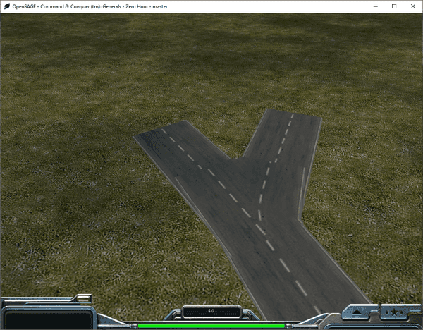
And now, finally, the crossings are done:

In the next post we'll tackle the curves.

